If you have any questions please call 973-728-7232.
Disconnect battery before installing:
The installation is done with existing headlight parts in the car. Both headlight sides install in the same manner but the supplied billet brackets are side specific and marked “P” for passenger side and “D” for driver side.
Remove your black plastic grille piece in front of the vacuum actuator. Each grille piece is mounted with two bolts on top of the nose section.
Remove the vacuum hoses from the vacuum actuators. Make sure you plug these hoses to prevent poor engine performance from the resulting vacuum leak.
Remove the following:
- Vacuum canister, mounted with two nuts on the vacuum canister bracket.
-C-clip
-Large coil spring
-Small flat steel bracket on door crank attached with one sheet metal bolt (aka overcenter bracket)
-Small square plastic bushing
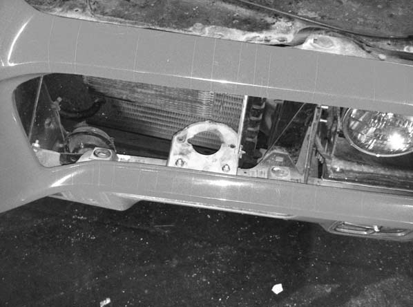
Your car should now look something like this:
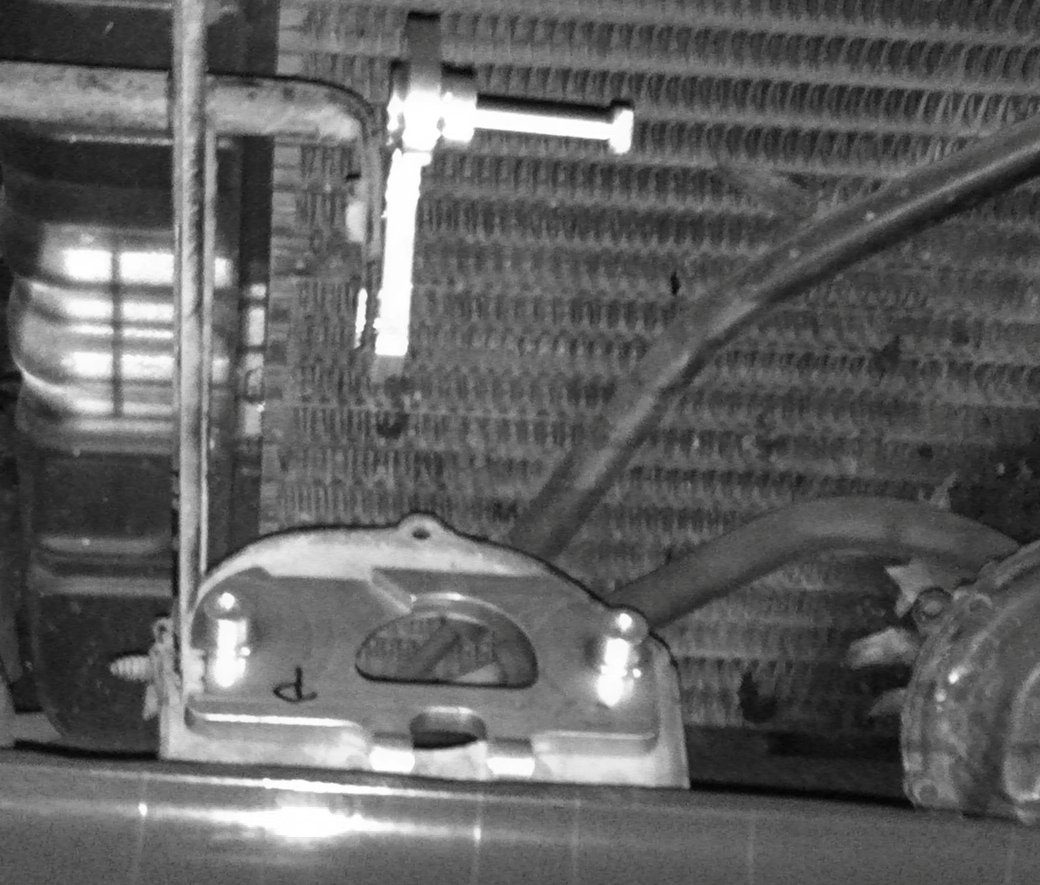
The original black “clam-shell” plastic bushing holding the door crank (see photo below) is often missing, partially broken or about to disintegrate. We have included this easily installed bushing along with other door bushings that may have deteriorated over the years. In most cases only the clam-shell bushing needs to be replaced.
Install the movable (top) actuator bracket (driver or passenger side specific) using the supplied 10/24 lock nut and flat-head screw. The bracket should fit perfectly in the square hole of the headlight door crank but may need to be squeezed in place with a pair of pliers.
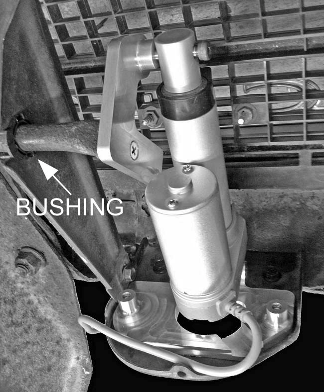
The fixed (lower) actuator bracket mounts to the original vacuum canister bracket using the two original vacuum canister mounting holes and supplied ¼” allen bolts. Mount the rear bracket with the actuator fork facing outward as shown in the picture below.
Mount the electric actuator to the actuator brackets using the supplied stainless shoulder bolts. The actuator is supplied in the half open position. A little grease on the shoulder bolt is recommended. Fine tune the actuator length to fit the actuator brackets by unscrewing door actuator ram. The actuator ram should be screwed out less than 8 full turns from screwed all in. Additional door adjustment can be obtained by adjusting the two original bolts holding the door crank to the door assembly.
Connect the actuator plug to the control box plug. The control box should be installed in an area protected from high pressure water spray and must be installed with the mounting ears facing down. A good spot to mount the control box is the bottom lip of the EndurA bumper right below the removed grille piece. The control box can be mounted using screws, industrial Velcro, 3M Car Accessory tape, silicone glue or epoxy.
WARNING! The battery MUST be disconnected before installing control boxes
WARNING!: Wires MUST be installed in the following order or damage may occur
Black wire - Is ground. Connect to any ground source (i.e. headlamp housing or radiator support).
Red wire - Is the power supply to the motor and must be connected to a permanent non-switched (always on) power source such as the directly to the positive side of the battery. Each control box needs a 4 amp fuse, which is supplied in the kit.
Yellow wire - Must be spliced to any low beam wire. In most cases the best splice point is right behind the plug connected to the three prong headlight bulb. Blue splice connectors are included in the kit for this.
White wire - Must be spliced to any high beam wire. In most cases the best splice point is right behind the plug connected to the three prong headlight bulb. Blue splice connectors are included in the kit for this.
Re-connect the battery, install the headlamp assembly and enjoy your hideaway headlights.
Final fine tuning of the door movement is completed by turning the actuator ram in or out. Sometimes it is easiest to make the final adjustments with the actuator ram partially open or partially closed by disconnecting the grey plug to the actuator while the actuator is in motion.
Notes:
Once the headlight doors are in motion, the headlight switch should not be operated until the headlight doors have fully extended.
The headlight door closing is delayed a couple seconds to allow flashing the headlights (to alert oncoming traffic) without the headlight doors shuddering.
To leave the headlight doors in the open position (i.e. for cleaning or lamp change) turn the headlights on and disconnect the grey plug between actuator and control box, then turn headlight switch off.
Specifications
Motor: DC, brushed. steel gear reduction
Electronics: SMT/“Through Hole”. Static and surge hardened
Voltage Range: 11 -16 Vdc
Temperature range: 0 - 220 F
Current draw: Motor - 3 A max. Electronics - <0.01 A
Short Protection: External fuse, non serviceable.
Wiring: Aviation type, Tefzel/Teflon coated, 16 gauge, 410 F max.
Connectors: Deutsch DTM, weatherproof
Control technology: Current sensing control with timed back-up safety circuit.
Disclaimer Proper installation should provide years of trouble free use. However, Retro-Electro, LLC assume no liability for any accidents, injury, damage or misfortune resulting from the use of this product.