If you have any questions please call 973-728-7232.
Disconnect battery before installing:
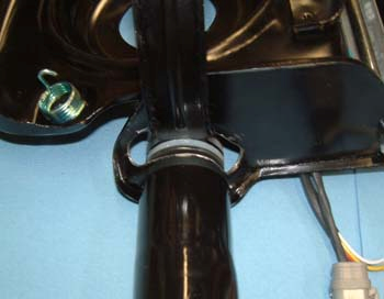
Remove the Rally Sport headlamp assembly and remove the vacuum actuator bell crank from the headlamp assembly.
Important: The motors can be mounted on either side. However, the electronic control box marked "D" mounts to the driver’s side, while the control box marked "P" installs on the passenger side.
Slide the supplied aluminum template over the bell crank hole and drill three motor mount holes as illustrated below.
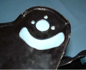
Cut a slot in the headlamp assembly as shown in the above picture. The headlamp arm must move fully within this slot from the closed to the open position. Important: Trim only the material necessary for the arm to move freely, excessive trimming will compromise motor mount rigidity.
Each motor has three threaded holes and a sealed 4th hole. Mount each motor using the thee threaded holes and the supplied ¼ “ 6-32 button-head bolts (blue Locktite recommended).
Important: This kit uses connectors designed for all weather use. However, the connectors are not designed to handle strain from pulling on the wire. Please connect and disconnect the plugs without pulling directly on the wires.
Install the supplied drive washers, plastic friction disks and motor arm onto the output shaft in the following order: steel drive washer - plastic friction disc - motor arm - plastic friction disc - steel drive washer.
Slide the supplied cone washer onto the output shaft followed by the supplied small washer.
Tighten the first jam nut to approximately 50 in/lbs, or tight enough to allow the plastic friction disks to slip if there is significant binding in the motor arm, Then jam the second jam nut onto the shaft.
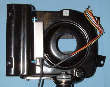
The control box installs inside the headlamp assembly as illustrated below. The control box is weather resistant but should be protected from direct water impact and tire spray.
Please install the control box so that the opening for the wires faces downward to prevent water from entering the control box.
The control box can be attached using double sided tape, such as 3M Car Accessory tape, silicone glue, epoxy or use zip ties through the mounting holes of the control box.
WARNING!: The battery MUST be disconnected before installing control boxes
WARNING!: Wires MUST be installed in the following order or damage may occur
Black wire - Is ground. Connect to any ground source (i.e. the headlamp housing).
Red wire - Is the power supply to the motor and must be connected to a permanent non-switched (always on) power source. Connecting directly to the battery or battery junction is recommended for the passenger side, while the horn relay works well for the driver side. The included 4 amp inline fuse must be used.
Yellow wire - Must be spliced to any low beam wire (tan wire on GM headlight plug).
White wire - Must be spliced to any high beam wire (green wire on GM headlight plug).
Re-connect the battery, install the headlamp assembly and enjoy your hideaway headlights.
Notes:
The motors may perform a closing cycle during initial operation or after power has been disconnected. This is normal. The headlight motor closing cycle is delayed a couple seconds to allow flashing the headlights lights without the RS doors moving.
Specifications
Motor: DC, brushed. All metal with steel planetary reduction
Electronics: SMT/“Through Hole”. Static and surge hardened
Voltage Range: 11 -16 Vdc
Temperature range: 0 - 220 F
Current draw: Motor - 5 A max. Electronics - 0.01 A
Short Protection: Internal fuse, non serviceable.
Wiring: Aviation type, Tefzel/Teflon coated, 16 gauge, 410 F max.
Connectors: Deutsch DTM, weatherproof
Disclaimer: Proper installation should provide years of trouble free use. However, Retro-Electro, LLC assume no liability for any accidents, injury, damage or misfortune resulting from the use of this product.